Note
These are my rough notes based on attending CS148. They might contain errors so proceed with caution!
Overview
So far we defined the radiant intensity as the amount of photons per solid angle, \(I(\omega) = d\phi/d\omega\). We defined the irradiance as the mount of photons per surface area, \(E = d\phi/dA\). We also defined the radiance (radiant intensity per area chunk) as \(L = dE/(d\omega \cos\theta_{\text{light}})\). Next we’re going to look at the color bleeding phenomena and then use it as a motivation to see how we can approximate light reflecting from materials in the scene we’re rendering.
Color Bleeding and Objects as Area Lights
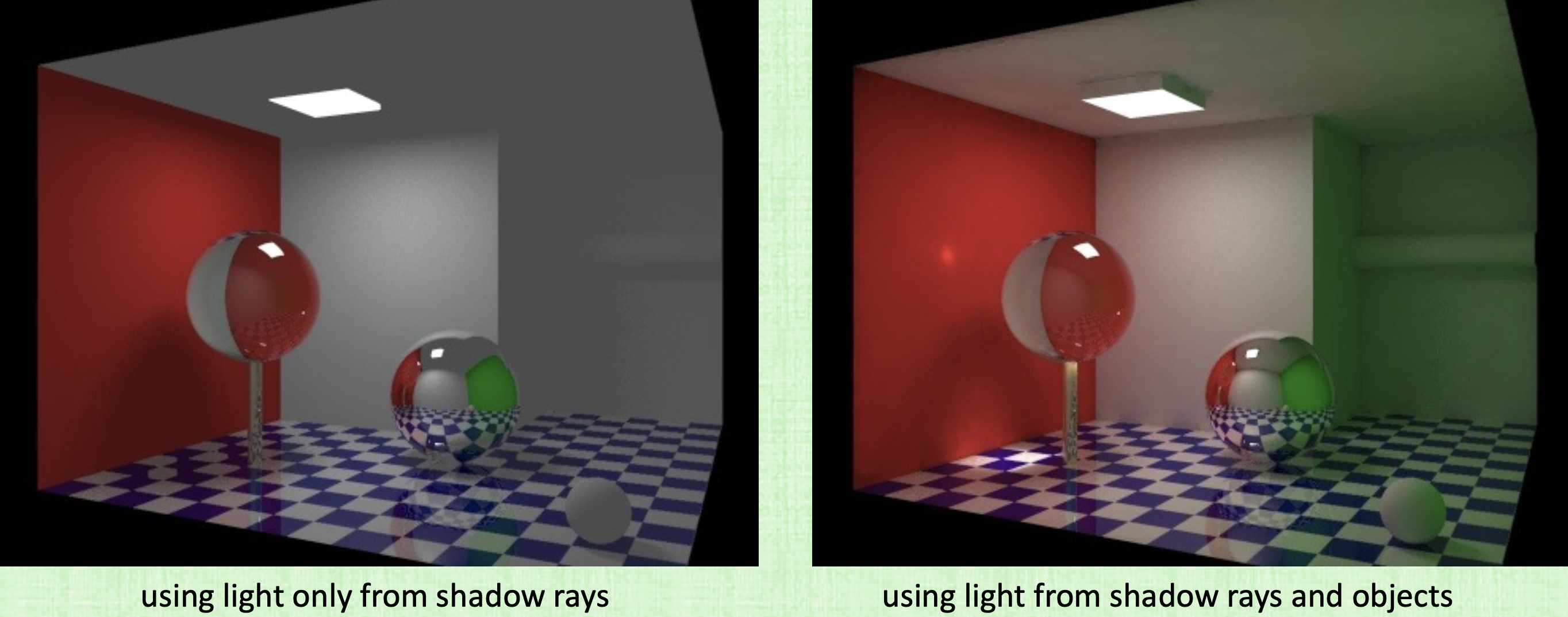
Light comes from all visible objects. One example is a shiny red car. Even though we don’t have a red light source, we can still see the effect on the objects next to the car for example (some reddish color). This is the affect of color bleeding.
To correctly render something, we need to know all the light that’s hitting it from every direction. So to model color bleeding with ray tracing, we treat all the objects in the scene as area lights. We basically need to know all the light that hits an object from every direction. How can do such a thing? The trick is to use a light probe (small reflective chrome sphere) and take a picture of it. This sphere will capture all the incoming light from all directions. So now when we place an object in the scene, we’ll render it using all the light from the chrome sphere.
Light/Object Interactions
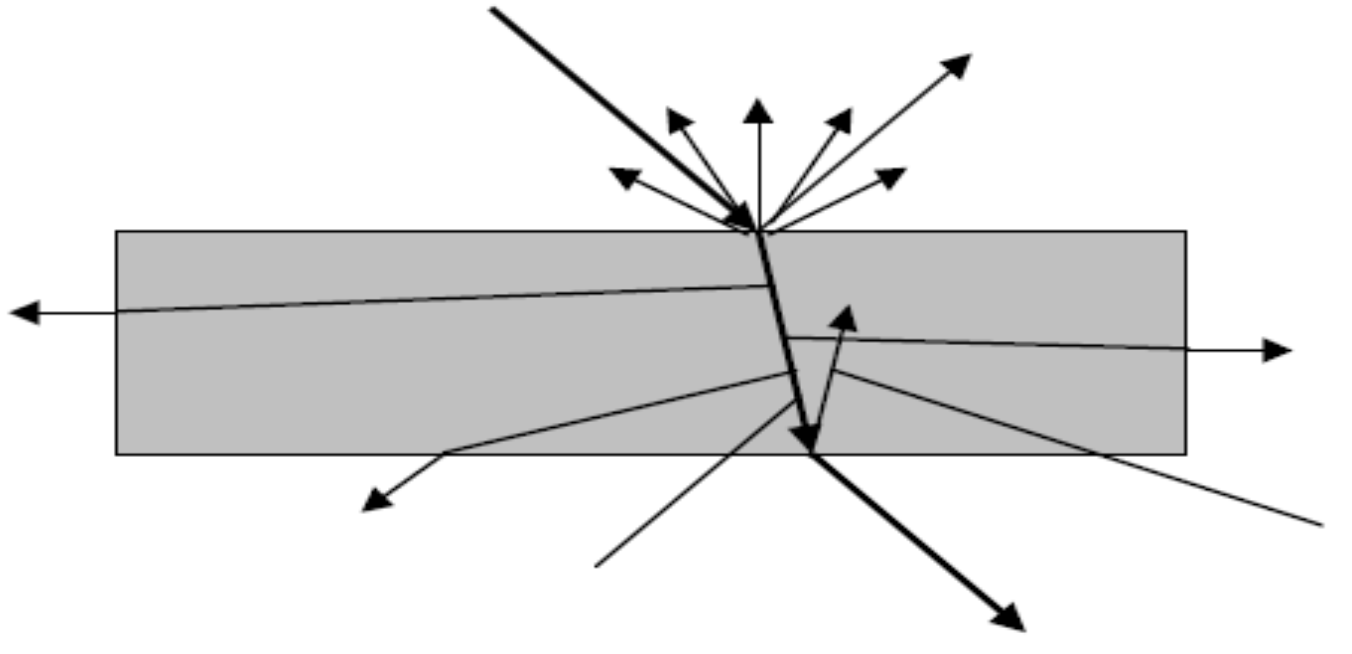
- When light hits a material, it maybe be: absorbed, reflected or transmitted.
- When light passes through a material, it maybe absorbed or scattered.
- When light exits a material, it maybe: absorbed, reflected or transmitted.
So light is complicated and for this reason, we come up instead with engineering approximations for light:
-
BRDF: The “Bidirectional Reflectance Distribution Function” models how light is reflected. It models everything that happens on the side of the surface where the light is coming from.
-
BTDF: The “Bidirectional Transmission Distribution Function” models how light is transmitted. It models everything that happens on the other side of the surface where the light is coming from. (won’t get focus in this class)
-
BSSRDF:
One example of the difference is this picture:
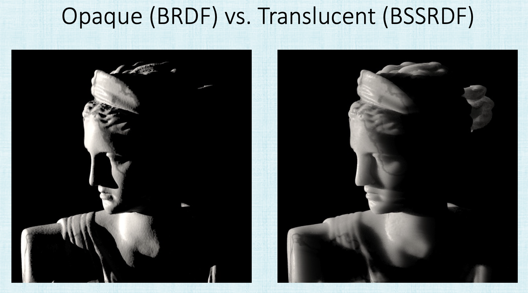
The bssrdf models this extra light getting inside the marble that is getting out and making it brighter. There are other examples in the slides.
BRDF
Again The “Bidirectional Reflectance Distribution Function” models how light is reflected. It models everything that happens on the side of the surface where the light is coming from. The BRDF depends on the following parameters:
where
- \(\lambda\) is the wavelength. (Though, we’ll only consider \(R,G\) and \(B\) since they’re what matters for humans to see)
- \((u,v)\) are the coordinates on the object’s surface. (We’re going to cheat with textures, more on this later)
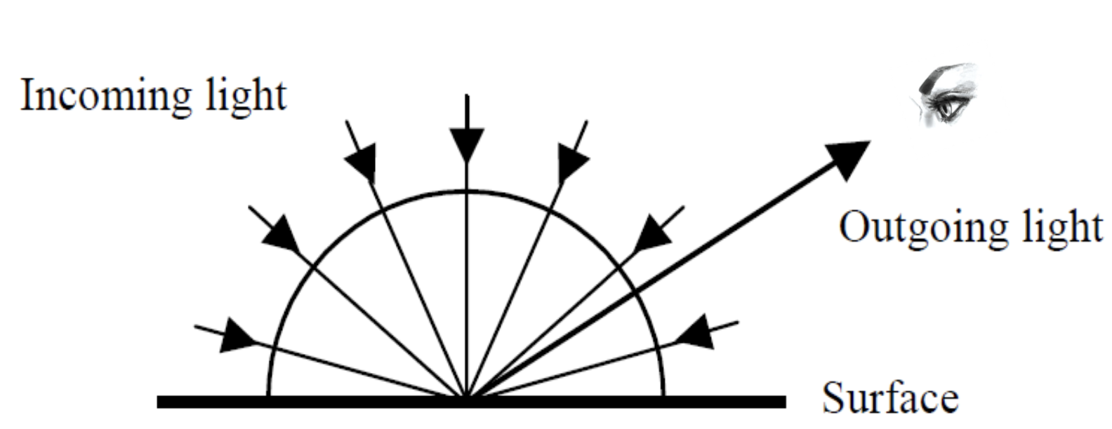
- \(\omega_i(\theta_i, \phi_i)\) and \(\omega_o(\theta_o, \phi_o)\) are the incoming and outgoing light directions parametrized by the 2D surface of a hemisphere.
So we really only care about the two parameters \(\omega_i\) and \(\omega_o\). Additionally, we’re going to compute the \(BRDF\) for each color channel separately so we’ll have 3 different equations for each color channel so \(BRDF_R(\omega_i, \omega_i), BRDF_G(\omega_i, \omega_i)\) and \(BRDF_B(\omega_i, \omega_i)\). These functions are functions of 4 variables (4D). For each \(\omega\), we depend on \(\theta\) and \(\phi\). The \(BRDF\) function can be written as,
That is the \(BRDF\) is the ratio of radiance \(Lo\) (light shinning off the surface) to the irradiance (light coming in hitting the surface.). \(\omega_i\) is the incoming direction. \(\omega_o\) is the outgoing direction. For each pair of directions, we’ll have a different \(BRDF\) function. What we get out is the amount of light.
So again, pick a point on the surface and pick a color. the \(BRDF\) function will tell us how much light bounced. It tells us the fraction of the “incoming light hitting that surface patch (irradiance)” that bounced in that direction \(\omega_o\). This is the “outgoing light emitted from a surface patch” (acting as an area light). So it is basically converting incoming light to outgoing light.
Measuring/Approximating a BRDF
The Lighting Equation
The total amount of light reflected in a single outgoing direction is the sum of the light reflected in that direction due to light incoming from every direction.
References
Fundamentals of Computer Graphics, 4th EditionCS148 Lectures