Note
These are my rough notes based on attending CS148. They might contain errors so proceed with caution!
Overview
So we casted rays from the camera until they hit some object and then again we casted shadow rays that go from the object until they hit a light to determine if they’re obstructed by another object and we didn’t need recursion in either case. But now for reflection and transmission (refraction), we’re going to need recursion. So two parts: The first part comes when we a shadow ray is cast to each light source and the total contribution from all light is accumulated using:
where
- \(V_{light}\) be 1 if the light is visible and 0 if the light is occluded.
- \(I_{ambient}\) gets added to a fully shadowed region. This happens when \(\prod_{lights}(1 - V_{light}) \neq 0\). This product is zero if there is at least one visible light source and not zero if all lights are occluded. So to summarize for part one we have:
The second part comes from reflections and transmissions. Mirror like reflections can contribute to the color at an intersection point. Transparency allows other objects to be seen through a surface allowing those objects to contribute to the color as well. So overall, we have:
Note that we don’t multiply directly the reflection or the transmission by the color.
Scaling Coefficients
To make nice pictures, we’re going to add extra scale factors that modify the light contribution. So let
- \(k_d\) be the diffuse light scaling factor
- \(k_a\) be the ambient light scaling factor
- \(k_r\) be the reflectlace color scaling factor
- \(k_t\) be the transmission scaling factor. So now we have
Reflection and Transmission Rays vs Shadow Rays
Similar to how we construct rays for shadow rays we’re going to construct a reflection ray and then let it intersect with the scene geometry. We will store the resulting color in \(L_\{\text{reflect}}\) and \(L_\{\text{transmit}}\). The difference is that for shadow rays, we’ll immediately multiply the light intensity by the material color and the scale factor. For reflected and transmitted rays, we’re not going to get the color directly. The color will depend on the color computed from the geometry that their rays intersect. These intersection points might additionally cast more rays to find the color which is computed via shadow rays, ambient, diffuse, additional reflection and transmission rays. This means that we need to terminate at some point because this process can go on forever.
Ray Tree Example
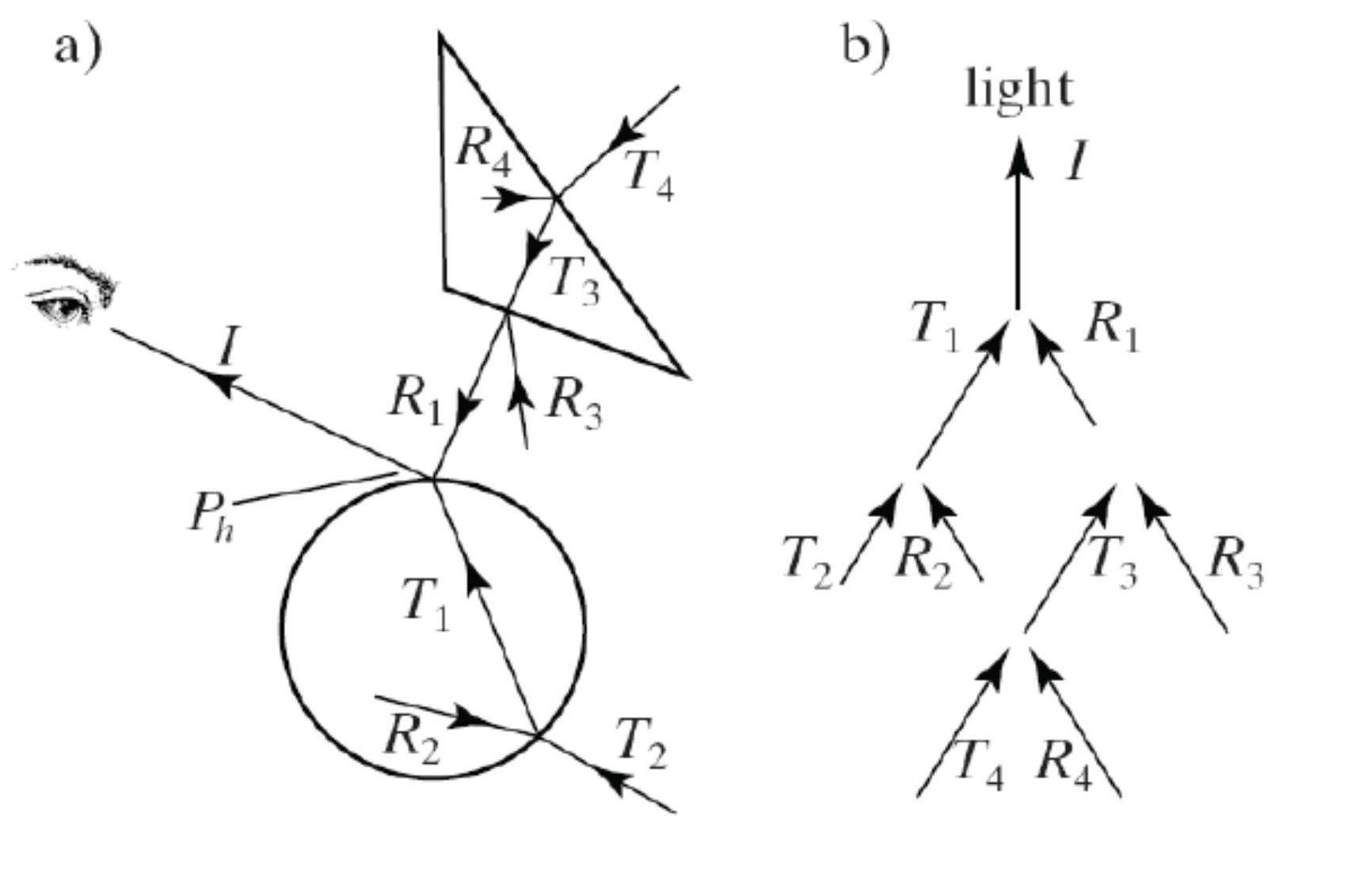
Suppose we have the above figure. We cast a camera/eye ray \(I\) until it hit the intersection point at the circle above. Now:
- It will cast a shadow ray to every light point and it will sum all these colors together. That’s the diffuse term. If it’s obstructed by all lights, then we’ll only add an ambient color.
- Next, we’ll figure out if the object we intersected is reflective. Also, we’ll ask if the object is transparent. In each case, we’ll recursively call our ray tracer to send rays \(T_1\) and \(R_1\). So go to step 0 for each ray. Once we have a result back. Now we’ll apply the scale \(k_r\) or \(1 - k_r\) depending if it’s transmitted or reflected.
Termination
So it can’t go on forever. We need some limits depending on the hardware. …
When we don’t have enough colors like in the case of rendering a house of mirrors or bubbles that don’t inherently have color, we don’t have difuse or ambient and we’re 100% relying on the light intensity. here we do need to end choosing arbitrary values to make the picture look good (realistic colors).
Reflected Ray
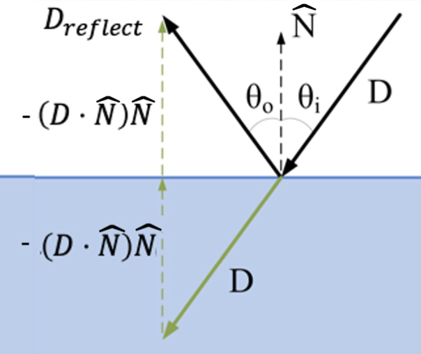
Given an incoming ray with origin \(A\), direction \(D\) and an outward unit normal \(\hat{N}\). (remember the ray and the normal both define a plane)
Given the above figure, consider the plane spanned by the ray direction \(D\) and the normal direction \(N\). Also since this is a mirror reflection then we know that \(\theta_o =\)\theta_{i}$$. Focus on the normal and ray direction below.
What is the normal component of v? If \(N\) is a unit vector, then this is just the dot product \(D \cdot N\).
The angle of incidence is defined by
So now we can geometrically construct a reflected ray. For a mirror refraction we want \(\theta_o = \theta_i\). So we want twice that angle. The reflected direction is the direction of the incoming ray minus that part from the figure, twice the angle in the normal direction. (???)
and the reflected ray:
Spurious Self-Occlusion
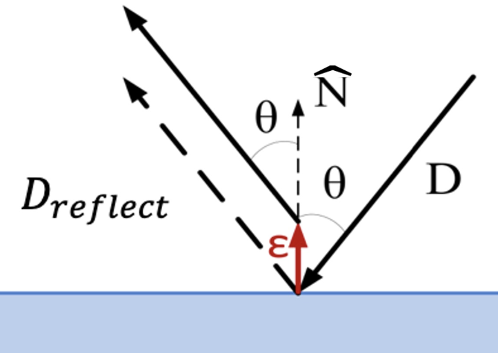
We’re going to have the same problem here like we did with the shadow ray. Same solution. Perturb the starting point of the reflected ray to \(R(t_{\text{int}}) + \epsilon\hat{N}\). HOWEVER, we don’t modify the ray direction (unlike shadow rays). This is because there isn’t a light source to point at.
So the new reflected ray is now
Need to be careful that the new starting point isn’t inside (or too close to) any other geometry
Transmission
![]()
Transmission is more complicated than reflection. The angles here are different because of the phase velocities. Based on Snell’s law we can written their relationship as,
Where \(\theta_1, \theta_2\) are the incoming/outgoing angles, \(v_1,v_2\) are the phase velocities, \(n_1,n_2\) are the indices of refraction.
Transmitted Ray
![]()
So now we need to send a transmitted ray. How do we do it?
- We have our original ray, \(R(t) = A + Dt\).
- \(\hat{D}\) is the unit incoming ray direction.
- The outward unit normal is \(\hat{N}\).
- \(\hat{T}\) is the unit tangent in the plane of \(D\) and \(\hat{N}\) and if you draw a circle around (???) you can constraint this to:
\(\hat{D}_{\text{transmit}}\) is the unit transmitted ray direction so that
some scary math here
but using Snell’s law, we get:
- If the term under the square root is negative, there is no transmitted ray (all the light is reflected, total internal reflection)
- doesn’t matter if \(n^1\) or \(n^2\) is bigger.
- we need to add an epsilon to avoid self intersection (but this time in the negative direction)
Total Internal Reflection
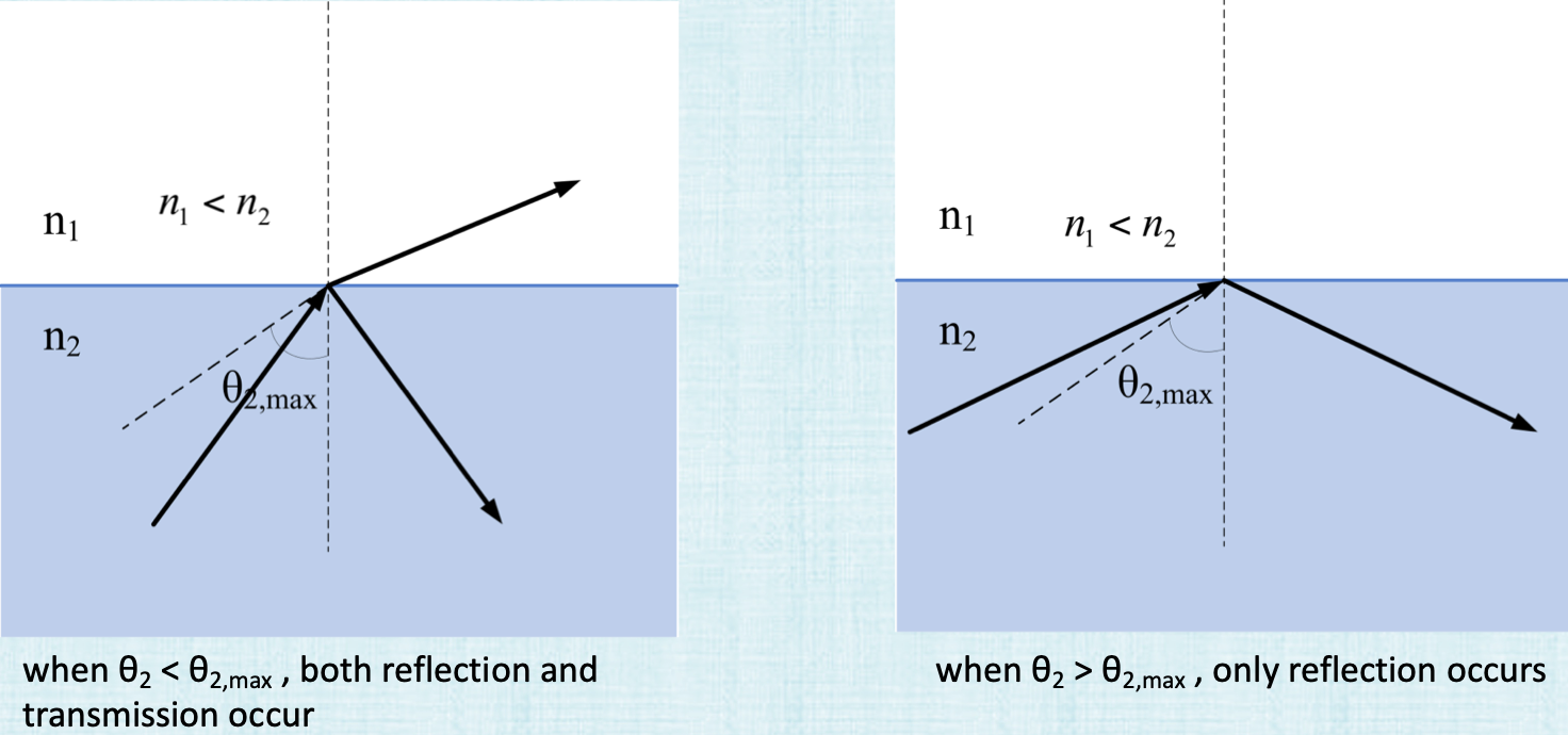
What happens above is that usually when \(\theta_2 < theta2_max\), we’ll have some reflected direction and some transmitted drection. But once you pass this critical \(\theta_{max}\), we won’t see a transmitted ray any more. This also only happens when light goes from a higher index of refraction to lower index of refraction (water to air), no light is transmitted. So to summarize: all the light reflects when
- when the incident angle exceeds a critical angle.
- we’re going from a higher refraction index to a lower one.
Critical Angle:

- \(\theta_1\) is the maximum angle for transmission.
- \(sin(\frac{\pi}{2}) = 1\) and Snell’s law becomes
This occurs when \(n_1 < n_2\).
- The amount of transmission vs. reflection decreases as the viewing angle goes from perpendicular (overhead) view to parallel (grazing) view.
Parallel -> more reflection. Perpendicular -> more transmission and less reflection.
Fresnel Equations
![]()
-
The proportion of reflection gradually increases as the viewing angle goes from perpendicular (coincident with the normal) to parallel (orthogonal to the normal)
- Light is polarized into 2 parts, based on whether the plane containing the incident, reflected, refracted rays is parallel (p-polarized) or perpendicular (s-polarized) to the electric field
- The Fresnel equations approximate the fraction of light reflected as:
Transmission (if it occurs) is calculated as the remaining light:
For unpolarized light (a typical assumption in ray tracing), assume:
Schlick's Approximation
- Approximate reflection via:
Conductors vs Dielectrics
- Conductors: (of electricity e.g. metal) mostly reflect light (low absorption, no transmission). The mount reflected doesn’t change with the viewing angle.
- So \(k_r\) can be approximated as a constant (independent of viewing direction) for conductors.
- In contrast, \(k_r\) varies significantly with viewing angle for dielectrics (e.g. glass, water).
Curved Surfaces
Attenuation
- Light is absorbed and scattered as it travels through material
- This attenuates the amount of light traveling along a straight line
- The amount of attenuation depends on the distance traveled (through the material)
- Different colors (actually, different wavelengths) are attenuated at different rates Example:
- Shallow water is clear (almost no attenuation)
- Deeper water attenuates all the red light and looks bluish-green
- Even deeper water attenuates all the green light too, and looks dark blue
- Eventually all the light attenuates, and the color ranges from blackish-blue to black
Beer's Law
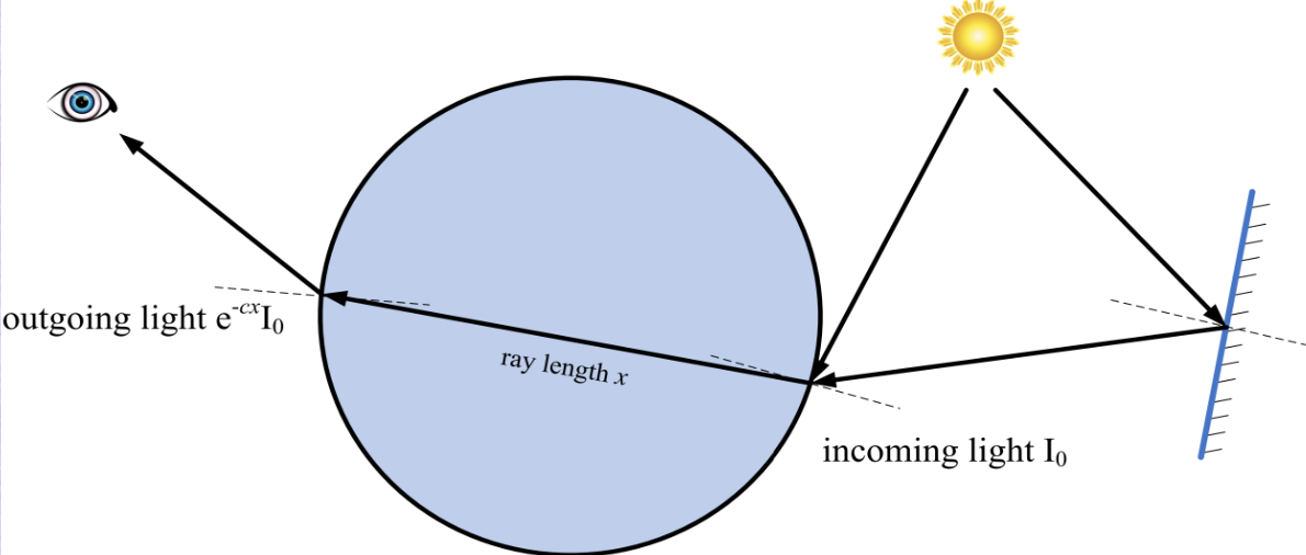
- For homogeneous media, attenuation can be approximated by Beer’s Law
- Light with intensity \(I\) is attenuated over a distance \(x\) via the Ordinary Differential Equation
where \(c\) is the attenuation cofficient. This ODE has an exact solution.
So the light gets multiplied by \(e^{-cx}\). x is the distance. A bigger C would mean more light goes away. So c is bigger for red light in water than green and blue.
- The color of a transparent object is described by three attenuation coefficients: \(c_R\), \(c_G\), \(c_B\)
- Shadow rays are also attenuated. So a shadow ray gets casted hits a transparent object before the light. this gets multiplied by \(e^{xc}\) as well
How to apply beer’s law:
Instead of just \(I\), have an \(I_R\), \(I_G\), \(I_B\) for each color.
Atmospheric Refraction
- Light continuously bends (following a curved path) as it passes through varying temperature gases (with varying density)
- The density variations cause similar variations in the index of refraction
bends away from the hot air.
to do this in a ray tracer. divide the air into layers and keep bending the light.
Iridescence
- wave feature of light (constructure and destructive interference).