Note
These are my rough notes based on attending CS148. They might contain errors so proceed with caution!
In Part 1, we’ve discussed the virtual world setup including the pinhole camera and how to place our 3d objects within the virtual world by applying transformations such as rotations, translations and resizing (Model Transformations). We’ve talked about homogenous coordinates to help do all of these transformations using matrix multiplication. In this post, we’ll now discuss how to go from the 3d virtual world to our 2d image but before that we’ll highlight the differences between two methods of rendering, the ray tracing method versus the scanline rendering method.
Ray Tracer
So now we have a virtual world with a number of objects it (some geometry) and we’re now trying to turn all of this of geometry into pixels on the screen. If we’re using ray tracing then:
- It starts at a pixel that wee want to know what color it should have. So we send a ray through the aperture out into the world. We’ll draw a straight line from the pixel through the aperture into the world. Once the line hits something. Now we’re going to pretend that all of this actually happened the opposite way. light hit the object and then it came through the aperture and finally onto the pixel.
- Before we press the button to take the picture, we have to have the world setup with geometry but as previously discussed, we use transforms to place the objects into the world. The objects stay in the amazon box. We just use the transforms to put them in the virtual however we want.
Scanline Render
For a scanline renderer:
- The renderer will take all the geometry from the world and push it through the aperture onto the image. (in our case, just toward the aperture since the image plane is in front of the aperture). We’ll take this geometry and squish it from 3d to 2d onto the image plane. We do this with a transform. A non-linear transform.
- A homogenous matrix will be used for this transform. Therefore, we can multiply this matrix by the transform matrix. The projection matrix will in fact be the last matrix in the transformations stack of matrices!
Big Picture
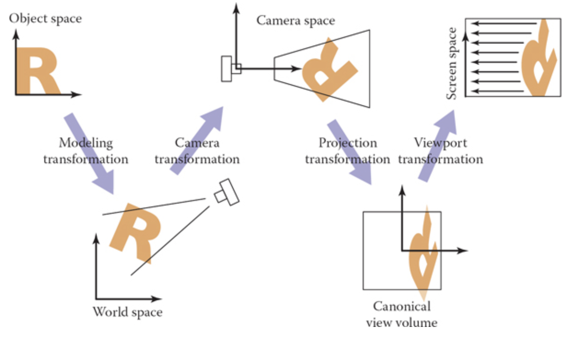
To render a picture:
- We need to transform the models into the virtual world via model transformations. Here we went from the “Object Space” to “World Space”.We did this already in part 1.
- From “World Space”, we need to go to “Camera Space”. This is where we will place the camera at the origin via some rigid transformation.
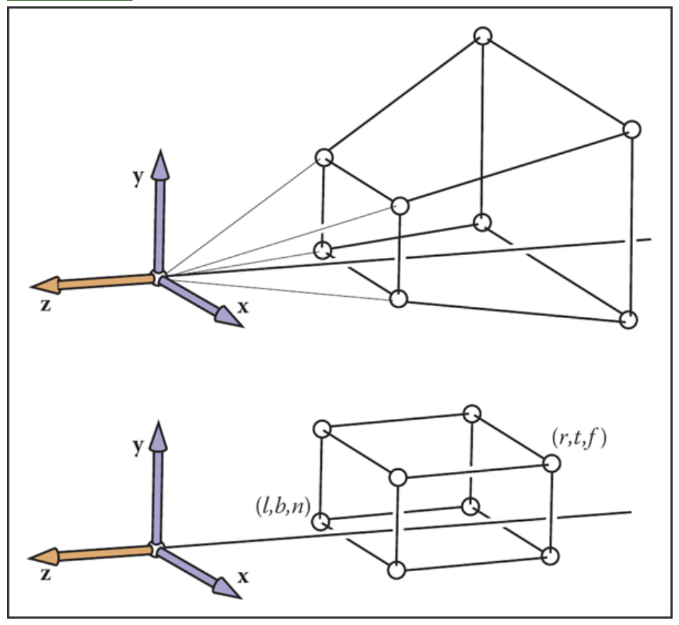
- Take the viewing frustum and apply a perspective transformation to shrink it into a viewing volume with boundaries at \([l, r]\), \([b, t]\), \([f, n]\).
- Take this viewing volume and scale/resize it to the canonical viewing unit volume with all these planes are now between -1 and 1. This transformation is called the orthographic projection transformation.
- Finally, there is a viewport transformation from go from the unit volume to pixel coordinates in “screen space”.
- The next transformation is the orthographic projection transformation. The viewing here is looking along the minus z-axis with the head pointing in the y direction. What we want here, is to take this viewing volumn with the left and right planes (\(x = r,l\)), top and bottm planes (\(y = t,b\)) and near and far plane (\(z = n,f\)) and convert this volume to what is called the canonical view volume. Note that we’re not doing any perspective projection yet.
(2) Camera Transformation
TODO. This is done to change the view point in 3D. We have three parameters here. The eye position \(e\), the gaze direction \(g\) and the view up vector \(t\). We’re going to skip this transformation for now.
(4) Orthographic Projection
Let’s skip (3) and talk about (4) since it’s simpler. Here we’ve already applied the perspective transformation and now we have this viewing volume that is not yet a unit volume. W’re just taking the viewing volume and converting it to a canonical volume. Here we’re going from the camera space to a canonical view volume. We’re going to scale and translate the viewing volume to a canonical volume. Note that we will not need any rotations here. It’s just scaling and translating. Here is the matrix that we will end up with.
(3) Perspective Transformation
Before applying the orthographic projection, we have applied a perspective transformation, shown above. (Image taken from the book in my references). So how do we do this? Let’s fix the z-axis below (image from the slides)
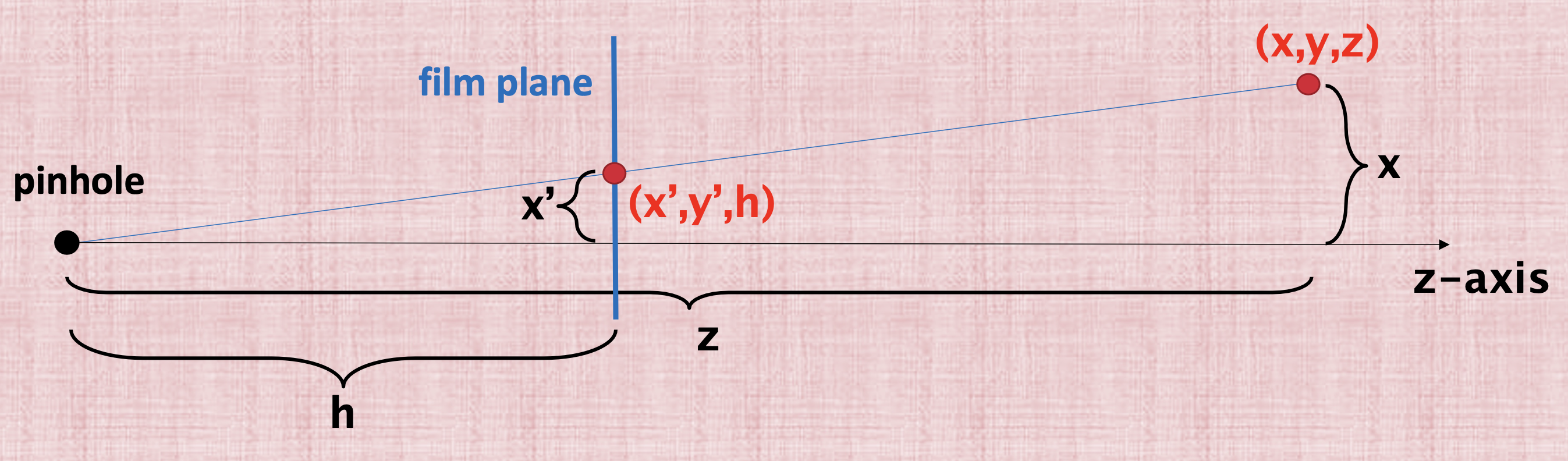
The key property of perspective is that the size of an object on the screen is proportional to 1/z. We start from \((x,y,z)\) and we need to find the coordinates \((x',y')\) that will be used in the film plane. To find these coordinates, we can use the properties of similar triangles to derive the film x-coordinate,
and the film y-coordinate,
Dividing by \(z\) is non-linear and we want to use a matrix multiplication for this projection. So how do we solve this issue? We’ll use the same the trick that we used with translation which is homogenous coordinates.
Homogeneous Coordinates Revisited
The homogenous coordinates will allow us to express this transformation from world coordinates \((x,y,z)\) to film coordinates \((x',y')\). So previously we expressed translations with homogenous coordinates, we said that for points, we’re going to add a fourth coordinate that is equal to 1 and for vectors we’re going to add a 0. This is just to make translation works as a matrix multiplication. So instead of just “bolting” a 1 (per the book), we’re going to define this 4th coordinate as the denominator of the \(x\), \(y\) and \(z\) coordinates. So for example:
is the point \((x/w, y/w, z/w, 1)\).
Prespective Matrix
So what we want is derive some matrix in order to go from \(h(x/z)\) for example to \(x'\), shown below
One idea that will get rid of the division is to use the forth coordinate for storing this \(z\) value just as we saw in the previous section. Additionally, we can put the \(h\) factor in the matrix where the scale factors go since we’re we’re scaling. To write this in matrix form:
So now let’s study this matrix. First of all, the forth row has a 1. This 1 is there to save the \(z\) coordinate so now we have \(w'=z\). This is really important and the trick that we need to do the division. So now we have \(w'=z\). Let’s now multiply the first row and see what it does. \(x'w' = hx\). Since we agreed that the forth coordinate will be the denominator then we get exactly what we wanted \(x' = hx/z\) as we wanted. A similar calculation can be done for the \(y'\) coordinate in the second row.
What about the mysterious third row? we have
So technically here \(a\) and \(b\) can be zero and we’ll be projecting this fine. We don’t need them really. So why bother? The idea here is that we might have two objects splattered on the screen with one object infront of the other. But all these geometrics are now squished together because we use the matrix, all of the \(z\) values will just be \(h\) where the film plane is in here,
We lost the information that will tell us which object will have a lower or higher \(z\) value. So the idea here is use that third row to preseve these values (the notion of what’s infront and what’s behind). a smaller \(z'\) will mean it’s infront, a higher means it’s behind.
Let the near clipping plane be \(n\) and the far clipping plane be \(f\) of the viewing frustum. (Usually \(h\) is just \(n\) but doesn’t have to be). We also want to preserve the clipping planes so that when \(z=n\), \(z'\) is also \(n\) and when \(z=f\), \(z' is also\)f$$. So now we have these two equations,
and
The solution to these equations are \(a=n+f\) and \(b=-fn\). So the perspective matrix is now:
References
Fundamentals of Computer Graphics, 4th Edition
CS148 Lectures